ATTiny85 RGB Christmas Tree
Thursday, 5 December 2024
Over a few years I've built various electronic projects involving RGB LEDs. These LEDs are controlled using a serial protocol which allows them to be set to any colour. The most famous LEDs of this sort are the WS2812B LEDs, which are often known as "NeoPixels", though there are many other types. They appear on boards such as the Circuit Playground Express and you can also buy them individually, in strips or in rings at many online stores. Just searching eBay for "WS2812B" will turn up hundreds of possibilities.
Combined with a microcontroller, RGB LEDs can produce some wonderfully colourful effects, and so they make interesting decorations and gifts. They can be used in place of candles, put into lanterns or tea light holders, and a few of the ones I've made are on my Github page along with the source code that drives them.

Today I am writing about the 3D RGB Christmas tree for Raspberry Pi. This has 25 RGB LEDs on a tree-shaped 3D circuit board. The tree looks good, especially with the lights flickering in Christmas colours. But it is intended to plug into a Raspberry Pi, and it seems a shame to dedicate a powerful and flexible computer to such a simple task. Even a smaller Pi device like the Pi Zero still seems like overkill.
I wanted to see if I could drive the 3D Christmas tree using a microcontroller. The size and cost could be small, and it would become a nice Christmas decoration and self-contained Christmas gift.
Looking for something smaller than an Arduino, I found the ATTiny85, which is a microcontroller in an 8-pin microchip. This device has Flash, some RAM, some I/O pins and an internal clock generator which means that it can operate without any external components besides a power supply! It is like a "little brother" to the microcontrollers used in Arduino boards - the CPU is similar, but the surrounding hardware is minimal.
In order to see if this would be feasible, I looked at the Python examples for the RGB Christmas tree to find out what protocol was used to control the lights and which of the Raspberry Pi header pins are used. Only a few of the Pi pins are actually required:
- MOSI (SPI data) - Broadcom GPIO pin 12 on Pi - Physical pin 32
- CLK (SPI clock) - Broadcom GPIO pin 25 on Pi - Physical pin 22
- 5V - Physical pin 2
- GND - Physical pins 6, 9, 14, 20, 25, 30, 34, 39
Only two SPI pins need to be connected, and I found that I could operate the RGB LEDs using any microcontroller, not just a Raspberry Pi. As an initial test, I used a Pico, as it's quite easy to use SPI on a Pico with SPI library functions in the Pico SDK. The protocol is straightforward:
- Send 4 zero bytes
- For each of the 25 LEDs:
- Send the start/brightness byte: value 0xe0 .. 0xff
- Send blue (0x00 .. 0xff)
- Send green (0x00 .. 0xff)
- Send red (0x00 .. 0xff)
- Send 5 zero bytes
I became fairly sure that an ATTiny85 could be used. Only two pins are required (MOSI and CLK) and because the RGB LED protocol uses a synchronous (clocked) bus, exact timing is not important.
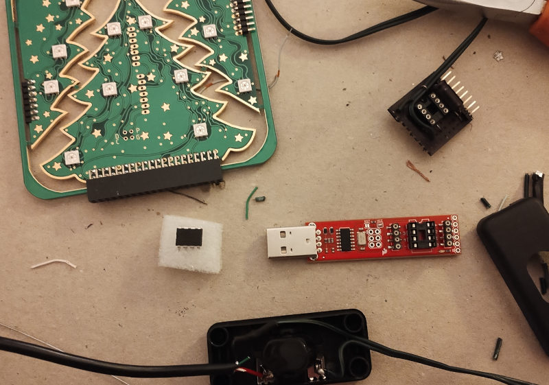
Next, I bought the Sparkfun AVR programmer which can be used to reprogram the ATTiny85 Flash memory. This is necessary because the chip doesn't connect to USB or serial directly. It is possible to save money by building an AVR programmer using another device (e.g. Pico, Raspberry Pi), but I have previously found it is better to get a dedicated device for jobs like this, as it is more reliable, easier to use, and available for use in the future, unlike something that is assembled temporarily from other parts.
Then I ported an existing Arduino program for controlling RGB LEDs to run on the ATTiny85. Only a few adaptations were necessary:
- Instead of driving the LEDs via the WS2812B protocol, SPI is used. I used "tinySPI" for this.
- The physical locations of LEDs in the Christmas tree is somewhat unpredictable. LEDs in a ring are in clockwise or anti-clockwise order, so a rotating rainbow effect can simply consider LED N+1 to be adjacent to LED N, but for the tree, LED N and N+1 may be entirely different places. I needed to discover the order by testing each LED in turn. Then I created a remap table so that the existing code can treat LED N and N+1 as adjacent.
- The ATTiny85 is slower than the microcontrollers used for earlier projects; this is a particular problem when the code calls the rand() function to generate a pseudorandom number. I was able to increase the clock speed to 8MHz by following these instructions to update some hidden settings in the device, but even at this speed, rand() was quite slow and I needed to rewrite part of the code to call it less frequently.
The next step was to assemble some physical hardware. It's important to have a plan for this, even if it is very simple, so I started with a circuit diagram:

As you can see, very few external components are required. I added a switch to select between three modes (this is optional) and a capacitor to absorb the electrical noise that is produced when the RGB LEDs change state, as this could cause the microcontroller to reset.
I wanted to use a single circuit board which would plug directly into the pins of the RGB Christmas Tree, which are intended to fit the 40-pin Pi header. But only four pins are really needed, and three of them are close together and on the same row: 32 (MOSI), 30 (GND) and 22 (CLK). The power connection (pin 2) is some distance away, but I had a different plan for that. A small wire would be added from an unused pin (e.g. 18) to connect it to pin 2. Then, all of the required pins would be close together.
I used stripboard with a 0.1" pitch (matching the ATTiny85), measuring 9 by 9, with tracks running from left to right, and drew this on squared paper:

This is a top-down view. The right-hand side of the diagram shows the 9 pins which connect to the tree. Breaks in the tracks are marked with X. There is space for a switch on the left-hand side, which controls the LED pattern. Components required are:
- Stripboard with 9 tracks and 0.1" spacing. You can get a larger section and cut to size with large wire cutters.
- Single row of at least 9 header pins with 0.1" spacing. This is similar to the pins on the RPi, but only a single row is needed.
- 10μF capacitor
- 8 pin DIP socket
- ATTiny85 in 8 pin DIP form factor
- A PCB-mounted switch with 0.1" pin spacing (optional)
- A power cable: an old USB cable is good for this
- 3D RGB Christmas tree for Raspberry Pi
- Small cable tie
- Solid core wire
- Solder
- Inline light switch (optional)
- Heat shrink tubing (optional)
The tools required are:
- Wire cutters, pliers
- Soldering iron
- ATTiny85 programmer
- Stripboard track cutter
- Black permanent marker e.g. Sharpie
- PC with Arduino IDE and drivers for the ATTiny85 programmer
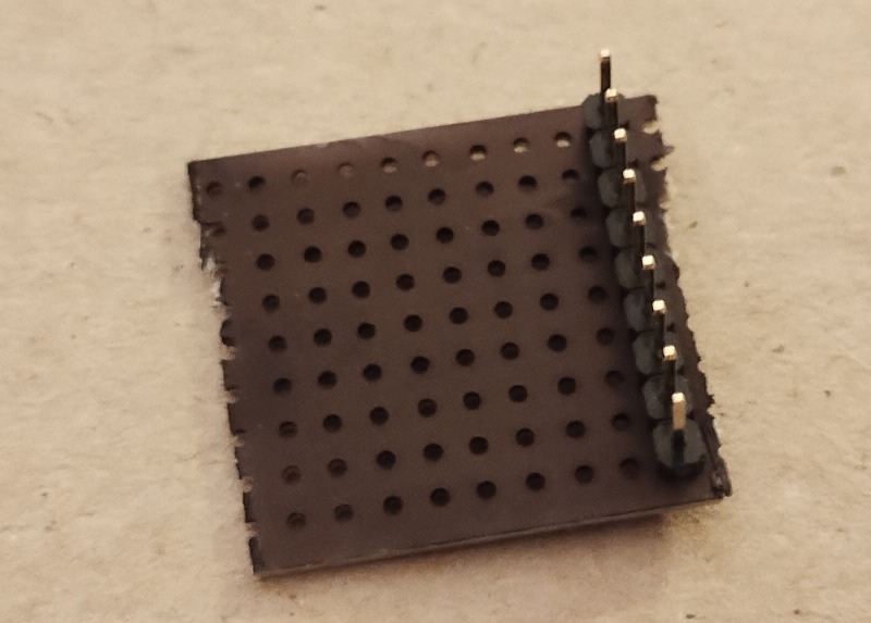
I began by cutting the stripboard to produce a 9 by 9 square, and then I used the permanent marker to make the surface black, so that the circuit board is less visible as part of the decoration. Next I soldered on the header pins - these come in rows of 20 or more pins, but can be broken down as required.
Next I used some pliers to bend the 9 pins into a right angle.
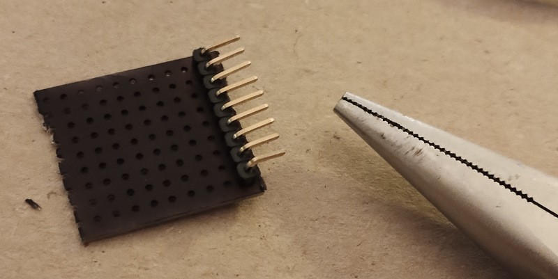
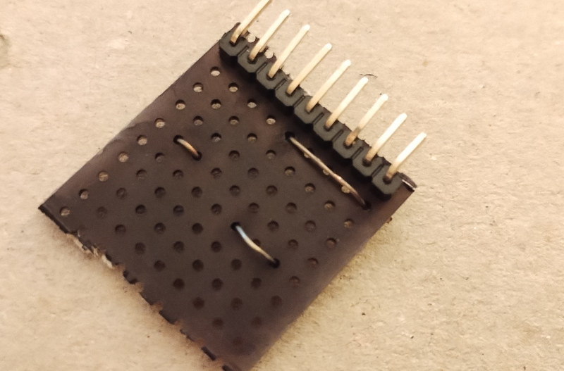
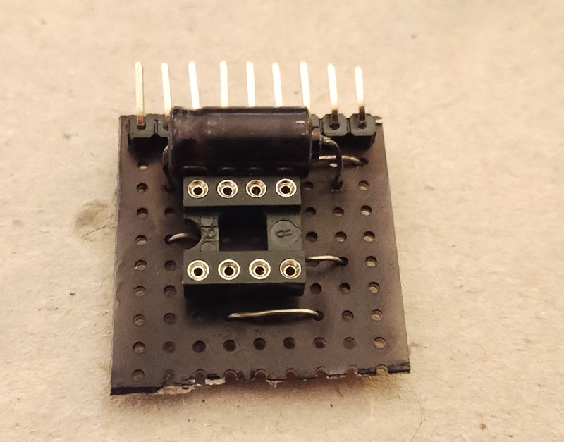
This completed the riskiest part of the assembly, as there is a reasonable chance that any pin might snap off! Next step was to solder on the link wires, which connect one part of a track to another. I used small pieces of solid-core wire for this, removing all insulation:
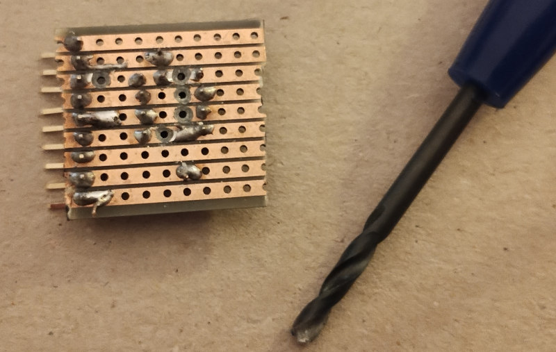
Then I added the 8 pin DIP socket, which is important for two reasons: firstly, it allows the ATTiny85 to be removed for reprogramming, if necessary, and secondly it avoids any need to directly solder the ATTiny85. Soldering any electronic device carries a risk of damage through overheating, and complex devices like microcontrollers can be particularly sensitive to this. Once the socket was added, I used a stripboard track cutter to break the tracks in the places marked in the diagram:
The next component is the capacitor. The capacitor was brightly coloured, so I used the permanent marker to colour it black before soldering. Here is the result:
Then, the power cable. I thought it would be a good idea to add an on/off switch, so I used an inline light switch intended for low voltage use. The power cable is an old USB cable, with the micro USB end cut off. Within the switch, only the red (5V) and black (ground) USB connections are used. The ground wire bypasses the switch, with heat-shrink tubing used for insulation around the connection. The 5V wire is switched:

The power connection from the switch was directly soldered to the circuit board, and I used a short section of wire to hold it in place.
Next, I used a multimeter to check for accidental connections between tracks and pins. Short circuits can permanently damage any of the components, so it's important to check before switching the power on. All adjacent tracks and pins should be checked.
Then, I programmed the ATTiny85 and added the Christmas tree. Very little assembly was required, the kit consists of three parts which fit together without soldering:
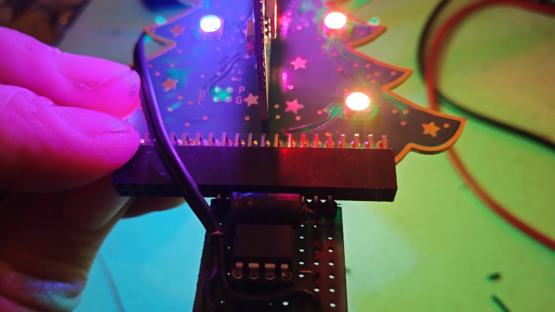
The last steps are to (1) join pins 2 and 18 together on the Christmas tree with a short piece of wire, (2) add the ATTiny85 and (3) plug in the circuit board. Then it can be powered up! Here is the first test:
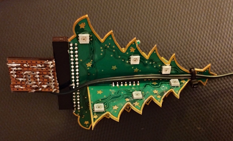
I used a cable tie to hold the power cable in place:
The final result as a 16x time lapse video: