Setup for Raspberry Pi Pico W and Segger J-Link Edu
Wednesday, 7 February 2024
Edit: Updated version of this article, also covering Pico 2 and with more detail about GDB.
At home, I have been working on a project involving Raspberry Pi Pico W. It's a microcontroller board, somewhat similar to small Arduino boards like Nano. It has plenty of RAM and Flash on board, enough to allow programming with MicroPython, and there are two CPU cores. There are lots of GPIO pins and a Infineon WiFi/Bluetooth chip so it's able to connect to almost anything.
Unlike the well-known Raspberry Pi boards, the Pico W does not run ordinary desktop or server operating systems (e.g. Linux). A Raspberry Pi is almost a self-contained computer, needing only a keyboard and monitor in order to be usable, whereas the Pico W must be programmed using another machine. The Pico W can run an OS intended for embedded systems, such as FreeRTOS, but typical applications do not use an OS at all. Instead the application runs directly on the hardware. But applications can still have powerful features. For example, the provided SDK includes examples of TCP services which use the lwIP networking stack.
The online resources for Pico W are really good. I wanted to connect a debugger, and because I already worked with a device with a Cortex-M0 CPU (Circuit Playground Express) I already had some of the hardware needed for debugging. Pico W has a Serial Wire Debug (SWD) port which provides debug access to the two CPU cores.
The physical SWD port consists of three holes in the PCB for some Pico boards, and pins can be soldered to these. On the board I have, a "Pico WH", there is a 3-pin header which can connect to a JST-SH cable, which you can buy from various places e.g. Pi Hut.
The SWD port can be connected to a Raspberry Pi via the GPIO pins as described in the Getting Started guide (currently chapter 6). This requires installing some free software on the Raspberry Pi. The SWD port can also be connected to another Pico device: this is then called a "Picoprobe" and Raspberry Pi provides some downloadable firmware for this. The Getting Started guide also describes the Picoprobe (currently Appendix A). A third option is a dedicated debug probe, such as Adafruit's Pico debug kit, or Segger's J-Link probe. These devices connect to a desktop computer via USB.
Whichever device is used, the associated software will provide a "GDB server" on a TCP port. GDB (or a debugger based on GDB) can connect to this port using a command like "target remote localhost:2331", and this gives access to the CPU core in the Pico.
I already had a J-Link Edu device because I previously worked with the Adafruit Circuit Playground Express (CPE). At one point I accidentally overwrote the boot ROM in the CPE. This bricked the device, and then I needed to use a debug probe to restore it, following these instructions. At the time there was no "Picoprobe", and I was not aware of any way to use a Raspberry Pi as a debug probe, so the J-Link Edu was the cheapest option. It is a versatile device and I expected I would probably need it again in the future. It can be used with other Cortex-M0 devices, including Pico and Pico W.
The J-Link Edu uses a tiny 10-pin ribbon cable with 1.27mm pin spacing. This is very delicate, the pins are really small and it's difficult to connect anything directly to it, so I use a breakout board (also here) which plugs into a standard 0.1" breadboard.
Segger's wiring instructions for Pico were somewhat confusing, because they specify pins on the full-size J-Link probe rather than the J-Link Edu. As I had some difficulty setting up the software, I wondered at first if I had made the right connections. But after some effort, I had it working. The correct wiring for the J-Link Edu is:
| Pico W debug pin | Breakout board pin | J-Link Edu pin | Debug cable wire colour |
|---|---|---|---|
| DEBUG SWCLK | CLK | 4 | red |
| DEBUG GND | GND | 5 | black |
| DEBUG SWDIO | SWIO | 2 | yellow |
| 3V3 - pad 36 | Vref | 1 | none |
An additional wire is needed to connect the 3V3 wire to Vref. The wiring may be seen in this photo:
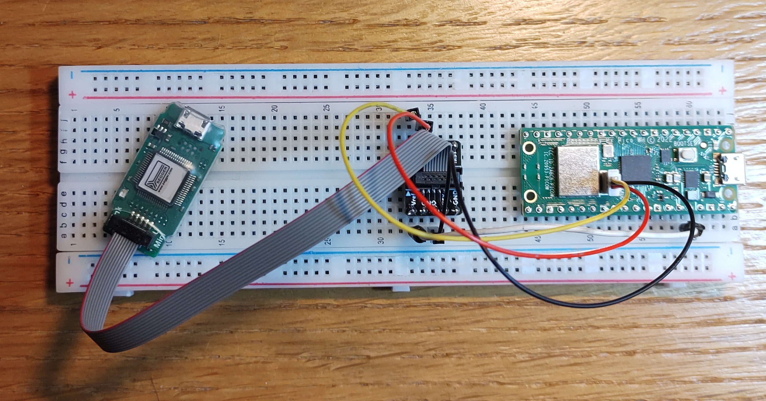
It is potentially confusing that the breakout board has an "SWO" pin and two other "GND" pins. These don't need to be connected. The red wire on the ribbon cable should line up with Vref (pin 1) at both ends.
Once the wiring is in place, you can use the JLink software. I used "JLinkConfig" to update the firmware on the JLink Edu probe and then "JLinkGDBServer" to run the GDB service. On Linux, run "/opt/SEGGER/JLink/JLinkGDBServerExe" as it has a useful GUI for the initial setup.
In the GUI, select target device "RP2040_M0_0" and target interface "SWD": all other settings can be left as defaults, though I would also tick "Localhost only" to prevent remote access to the GDB server (screenshot).
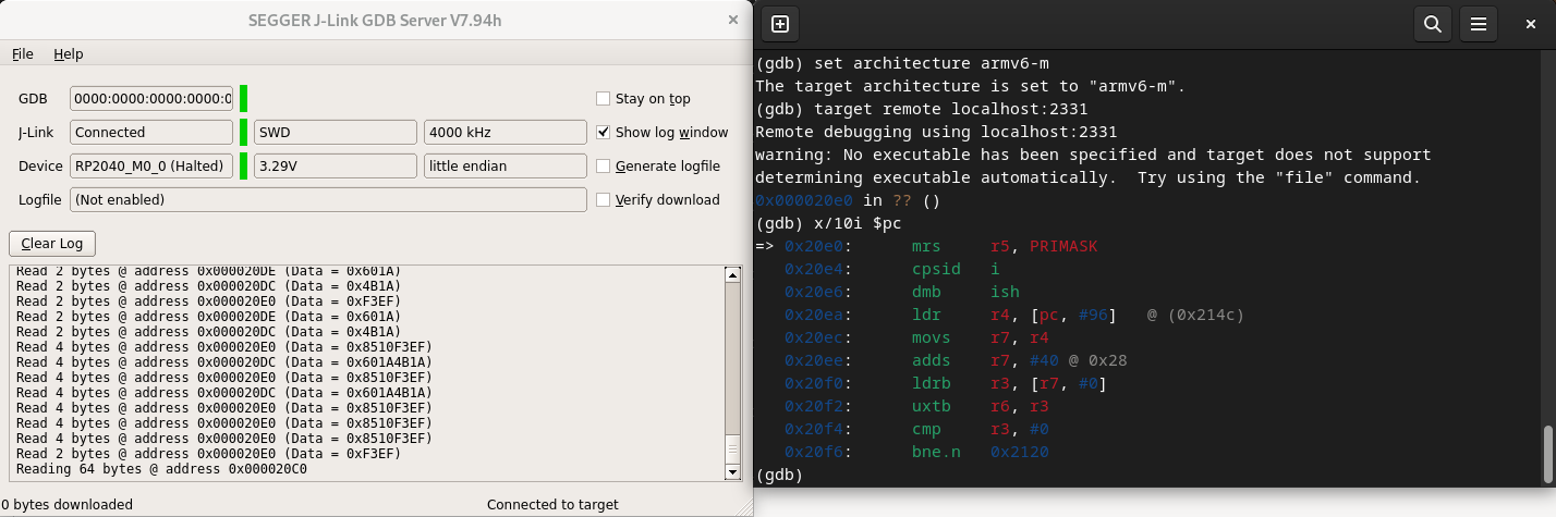
Below, you can see JLinkGDBServer and GDB running side by side. I have entered the GDB commands needed to set the architecture (armv6-m), connect to the server and then dump 10 instructions starting at $pc. (This is part of the Pico's bootloader ROM, which, I gather, cannot be overwritten by software!)
My problems with this setup turned out to be issues with the tiny J-Link ribbon cable. Unfortunately one of the connectors is not completely reliable, and JLinkGDBServer cannot always find the board, even with the correct settings and wiring everywhere else. I found I needed to move the cable around in order to get the connection to work. A replacement cable might solve this, unless the issue is actually with the connector on the J-Link board. In the meantime, it does work, given a little patience. If you have problems with your own setup, it may be a similar issue with the ribbon cable. The photo and instructions on this page may help to reassure you that everything else is correct.