S/PDIF Dynamic Range Compressor
Saturday, 6 August 2022
I had some fun building an S/PDIF tester using an FPGA so I thought I would begin a follow-up project to create a digital dynamic range compressor to normalise the volume of sounds from a PC. We have found it difficult to do this by hand, because although the Windows volume mixer allows levels to be set on a per-application basis, sounds from each application are not necessarily consistent. Videos on web pages are particularly bad - they are frequently too quiet or too loud.
I based this on the same FPGA as the previous project: the iCE40HX8K FPGA from Lattice. The target board is the iceFUN module from Devantech. This time the goal was not just an experiment but rather to create a physical device which could be installed permanently between a PC and an amplifier to manage the volume level. Now assembled within a box, here is the result:
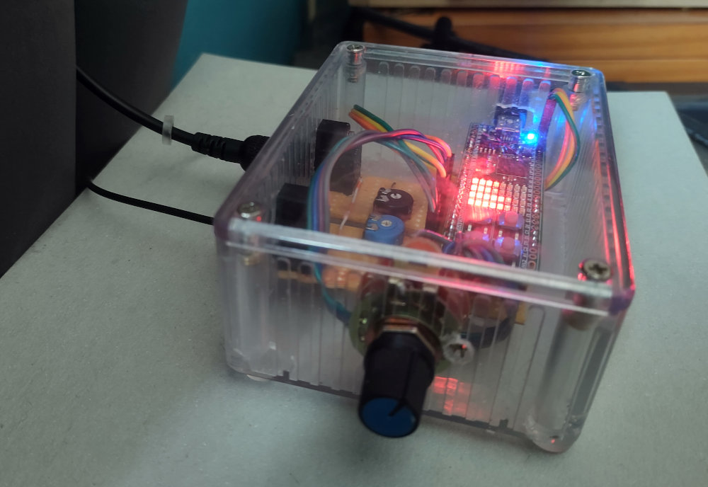
S/PDIF dynamic range compressor
The rotary control on the front of the box allows it to be set into six different modes to support six different use cases: loud music for exercise, quiet sounds at night, videos with lots of speech, etc. The volume of some of these modes can be adjusted by opening the box.
As before, the VHDL source code is on Github, this time with diagrams and details about the design of some of the components. This was a significantly more complex design, requiring:
- an output encoder for valid S/PDIF data, able to match the input data rate;
- a clock generator for the output encoder, supporting any required output frequency by matching the input;
- divider, multiplier and delay components;
- a serial line encoder/decoder ("UART") in order to communicate with the analogue-to-digital converters on the iceFUN board, these are used to set volume levels;
- a basic "user interface" which can display different information in each mode;
- many many more test cases!
audio out = audio in / peak level
All (digital) dynamic range compressors do a similar operation; they differ in how they determine the peak level and how they adjust it dynamically. There are all sorts of possibilities, and many opportunities to adjust parameters. The following screenshot from Audacity gives a typical example:
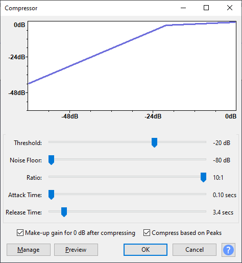
Audacity compression options
I didn't want the compressor to have so many options. I wanted it to be very simple, with only a few possible settings, making it easy to be sure that it was configured correctly and would always do the same thing. I also wanted to be sure that the output would never "clip" as a result of too much amplification, as this is very annoying.
Currently, therefore, the method of determining the peak level is very simple. The peak level is set to the current audio level whenever that level is greater, preventing clipping. At all times, the maximum value is 1.0 (so the compressor never actually increases the volume) and the minimum value is 0.0078 (this corresponds to -21.1dB, which is extremely quiet). The minimum is often called the "noise floor" and prevents the compressor amplifying very quiet sounds and background noises.
If the peak level is not set to either maximum or minimum, then it "decays" towards the minimum. This is done by dividing by a number that's slightly greater than 1.0. The number is calculated so that the volume increases by 1 dB per second, assuming a 48kHz input.
The compressor includes a delay. The purpose of the delay is to allow volume adjustments to be performed before the sound actually requires them. I used all of the "block RAM" resources in the FPGA (16kbytes) to implement a delay of about 85 milliseconds (assuming 48kHz input). The peak level's maximum is actually set from both the beginning and end of the delay.
This works well enough. The compressor adjusts immediately to loud sounds, preventing any clipping. It recovers gradually in quieter parts. Notification sounds, game sound effects and video sound from the PC are normalised nicely. Music generally works well, but this does depend on the genre: classical music doesn't work very well, with quieter parts sometimes amplified to the point where you can hear the orchestra breathing. For these cases, the device has a "passthrough" mode which disables the compressor.
I think that slightly better results could be obtained by low-pass filtering the undelayed input before using it to set the peak level. This would result in a more gradual change rather than an instantaneous drop in volume: this is a topic for further experiments.
One of the most pleasing aspects of this FPGA design is that it involves no software at all. There is no CPU. It relies on state machines described in VHDL to provide all of the control and sequencing needed to drive audio data through multipliers, dividers and comparators, draw status information on LEDs, and even send/receive serial data.
This would be a totally impractical approach if the design were built in discrete logic (e.g. with 74-series gates), where such tasks would surely be carried out by a microcontroller of some kind. Only the most time-critical operations would be done in pure hardware. However, these "hard wired" state machines become practical thanks to synthesis tools which quickly convert the VHDL into a "netlist" of logic gates with arbitrary complexity. The FPGA has enough space for the design to be made in this way.
An advantage of this no-software design is that the timing is totally predictable. In the current version, exactly 481 clock cycles are needed to process each sample. This never varies, because all of the components operate on a fixed schedule which does not change depending on the input. At the maximum sample rate of 96kHz, new samples arrive every 500 clock cycles, so the deadline is met comfortably.
This sort of design is hard to achieve with a CPU. It is possible to write programs so that they are "single path" (no branching) but this limits complexity quite drastically, taking away many benefits of software. In general, software brings variations in timing due to different paths through the program (i.e. branching) and it can be tricky to work out the worst case execution time, especially if the CPU handles interrupts or has an even slightly complex design (e.g. a pipeline). In pure hardware, with each component dedicated to a particular task, we need only a single measurement to determine both the best and the worst case.
The use of FPGAs for real-time embedded systems was suggested as an idea when I worked in academia. In some ways, it's a good idea. In an FPGA, tasks can be truly parallel, and use their own dedicated resources, making it much easier to reason about them and ensure that deadlines are always met. It is not a very practical idea in reality because of the cost of redeveloping software intended to run on conventional CPUs, but when a system is made from scratch, it is a possibility.